MIMMAXҽ�Ƶ�ԴMFU102MFU104MFU112MFU114MFU115
��˾���ƣ��麣��������������˾
���������ԴӦ�÷���>>ҽ�Ƶ�Դ
�������䣺mldzcx@tom.com
��ϵ�绰��0756-2219836
�� ϵ �ˣ����
����ʱ�䣺2020/2/26 15:45:12


���������ԴӦ�÷���>>ҽ�Ƶ�Դ
�������䣺mldzcx@tom.com
��ϵ�绰��0756-2219836
�� ϵ �ˣ����
����ʱ�䣺2020/2/26 15:45:12
��Ʒ����
��������-MINMAX�й�����������۰ļ���½�г���
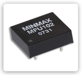
DC/DC��Դģ�� 1W, ��С��
MFU100ϵ��
��Ʒ���� |
|
||
|
|
|||
|
• �����ѹȷ�� |
��1.0%����ֵ |
|
|
|
• ��ѹ������ |
��1.2%����ֵ |
|
|
|
• ���ص����� |
��11%���ֵ |
|
|
|
• ������Ѷ |
100mV P-P ����ֵ |
||
|
• ��·����ģʽ |
���� |
|
|
|
• �����ѹ |
MBU100 �C 1kVDC |
||
|
|
MFU100 �C 3kVDC |
||
|
• Ч�� |
�ߴ�80% |
||
|
• �л�Ƶ�� |
90kHz ����ֵ |
||
|
• �����¶� |
-40��C to +75��C |
||
|
• ��Dz��� |
�ܽ�, 94V-0 |
||
|
• ƽ������ʹ��ʱ�� |
2 MHours min |
||
|
��Ʒ�ͺ� |
�����ѹ |
�����ѹ |
������� | |
|
Package Style |
|
|
| |
|
SIP |
DIP |
VDC |
VDC |
mA Max. |
|
MBU101 |
MFU102 |
5 ( 4.5 �C 5.5 ) |
5 |
200 |
|
MBU102 |
MFU103 |
9 |
110 | |
|
MBU103 |
MFU104 |
12 |
84 | |
|
MBU104 |
MFU105 |
15 |
67 | |
|
MBU111 |
MFU112 |
12 ( 10.8 �C 13.2 ) |
5 |
200 |
|
MBU112 |
MFU113 |
9 |
110 | |
|
MBU113 |
MFU114 |
12 |
84 | |
|
MBU114 |
MFU115 |
15 |
67 | |
|
MBU121 |
MFU122 |
24 ( 21.6 �C 26.4 ) |
5 |
200 |
|
MBU122 |
MFU123 |
9 |
110 | |
|
MBU123 |
MFU124 |
12 |
84 | |
|
MBU124 |
MFU125 |
15 |
67 | |
����������������չʾ����Ϣ�ɻ�Ա�����ṩ�����ݵ���ʵ�ԡ�ȷ�ԺͺϷ����ɷ�����Ա���𡣵�Դ���߶Դ˲��е��κα�֤���Ρ�
��ҵ��Ʒ��

��Ȩ����©2004-2026
��Դ���� ��ICP��12060667�� ������IE5.5���ϰ汾 1024��768�ֱ��������
 ��վ����0755-82905478 18025374360 ���棺0755-82905459 E-mail��customer@cps800.com
 �����ϵ��0755-83736095 82905136 18025374378 ad@cps800.com service@cps800.com
�ر�